Thanks for watching
Hope you have a great time
Please, like, comment and subscribe for more!!
-------------------------------------------
VIDEO: Rex Ryan Is 'Pissed Off' at Trump for NFL Comments | CaCao TV - Duration: 4:08.
VIDEO: Rex Ryan Is 'Pissed Off' at Trump for NFL Comments
Rex Ryan when he was coach of the Buffalo Bills.
Rex Ryan, the former coach of the Buffalo Bills and New York Jets football teams, declared that he's "pissed off" at President Donald Trump for Trump's comments about NFL players who "take a knee" during the National Anthem.
Ryan is a commentator ESPN's Sunday NFL Countdown. He used that platform to criticize the president; the comments drew attention because Ryan has previously been a Trump supporter. You can watch the video of what Ryan said on ESPN here:.
Let me tell you, I'm pissed off, I'll be honest with you. I supported Donald Trump.
I sat back when he asked me to introduce him at a rally in Buffalo, I did that. But I'm reading these comments, and it's appalling to me.
And I'm sure it's appalling to almost any citizen in our country. Calling our players SOBs and all that stuff.
That's not the men that I know. Men that I know in the locker room, I'm proud to be associated with those people.
I apologize for being pissed off, but guess what, that's it. Because right away, I'm associated with what Donald Trump stands for and all that because I introduced him. I never signed up for that. I never wanted that.
That doesn't mean I support 100-percent of the things he says, and clearly this is a case.
Trump started the war of words with the NFL on Friday, calling players who don't stand for the National Anthem a "son of a b-tch. " He doubled down on Twitter over the weekend.
On Sunday, Trump again called for NFL owners to fire or suspend players who don't stand for the Anthem. However, multiple owners have since defended their players' right to protest.
Specifically, Trump said on Friday, according to New York Upstate, "Wouldn't you love to see one of these NFL owners, when somebody disrespects our flag, to say, 'Get that son of a bitch off the field right now, out, he's fired.
He's FIRED!' You know, some owner is gonna do that. He's gonna say, 'That guy disrespects our flag; he's fired.' And that owner, they don't know it. They don't know it. They're friends of mine, many of them. They don't know it.
They'll be the most popular person, for a week. They'll be the most popular person in this country.". Ryan, while Buffalo Bills coach, had introduced Trump at a rally in 2016 in Buffalo, New York.
At that time he said, according to New York Upstate, "There's so many things I admire about Mr Trump, but one thing I really admire about him is, you know what, he'll say what's on his mind.
But so many times, you'll see people, a lot of people want to say the same thing. But there's a big difference.
They don't have the courage to say it. They all think it, but they don't have the courage to say it.".
-------------------------------------------
M10 Video 3 Creating Complex Symbols - Duration: 6:25.
in this video you will continue to create symbols using the same file from
the previous video called symbols to DWG you will learn how to create a section
cut symbol to see what a section cut symbol looks like take a look at the far
right of the drawing this symbol is used to denote a section geometrically a
section is a horizontal orthographic projection of a building onto a vertical
plane with the vertical plane cutting through the building the solid arrows
around the circle indicate which way the section is facing in this case the
section is facing left the bottom number indicates what page number the section
will be found whereas the number at the top denotes what number the section is
on the page we will be creating this symbol at a scale of 1 to 50 if in the
future you need to use this symbol on a drawing which will be displayed at a
different scale you will need to resize a symbol accordingly begin by drawing a
circle 700 millimeters in diameter next draw a horizontal line dividing the
circle into two equal halves
next draw three lines each 275 millimeters starting at the top left and
bottom quadrants of the circle and extending away from the circle like so
connect the endpoints of these lines with two angled lines like so now let's
add a solid hatch to create the arrow select the hatch command from the ribbon
or use the shortcut H on your keyboard click on solid up in the ribbon and
apply it to the two triangles around the circle great our arrow for the section
symbol is complete next we will add two block attributes to the top and bottom
half of the circle so that we can denote on what page the section can be found
and what number the section drawing will be on that respective page from the
block drop-down menu click on define attributes for tag right section for
prompt right drawing number and for default right xx
next make sure to select center in the justification drop-down list so that the
tag can be centered in the circle click OK and place the new attribute in the
top half of the circle next complete the same series of commands for the bottom
of the circle activate define attribute
for tag right section two for prompt right page number and for default right
xx once again make sure to select Center from the justification drop-down list so
that the tag can be centered in the circle click OK and place the attribute
in the bottom half of the circle lastly select the entire furniture tag and turn
it into a block once you've activated the block command name your block as
section cut symbol and select a base point at the center of the circle once
you've done that go ahead and click OK
I'm currently getting a message saying the block definition has changed do you
want to redefine it this is because I've already done this step previously it's
very possible you may not get this if you do go ahead and click redefine go
ahead and click OK to accept the values of X X under page number and xx under
drawing number your section symbol is complete at any point you can double
click on it and change the values in the page number as well as the drawing
number
you can now use this symbol to indicate where sections and elevations are taken
through and on what page they can be found if you take a look at the plan to
the left you can see that a section is identified as cutting through the dining
room great work save your drawing as symbols 3 dot DWG
you
-------------------------------------------
Alexandra Sublet poste sur Instagram une video de ses enfants qui courent - Duration: 1:30. For more infomation >> Alexandra Sublet poste sur Instagram une video de ses enfants qui courent - Duration: 1:30.
 -------------------------------------------
M10 Video 2 Creating Simple Symbols - Duration: 5:46.
in this video we will discuss the creation of simple symbols such as the
ones discussed in the previous video go ahead and open the file named symbols 1
dot DWG in this file you will be creating new furniture tags at a scale
of 1 to 50 if in the future you need to add tags to a drawing which will be
displayed at a different scale you will need to resize the tags
accordingly let's begin with furniture tags furniture tags are often denoted
with a circle and a combination of letters and numbers inside which refer
to a legend that provides further information about the product begin by
drawing a circle 300 millimeters in diameter anywhere on your drawing canvas
remember when drawing blocks make sure to draw them on the layer 0 and then
place them on to other layers after you've executed the block command if you
draw them on any other layer to begin with the color of the layer you
originally drew the block on will remain even when you move the completed block
from one layer to another next let's define a block attribute for the
furniture tag click on the drop down arrow on the block panel to expand it
hover your mouse over the first icon to ensure it is define attributes if it is
go ahead and click on it an attribute definition dialog box will open in the
tag box write tag in the prompt right furniture tag in the default box right
xx also make sure to select a middle in the justification drop down menu this
will centre our text inside the circle click OK now zoom closely to your circle
and place your text in the middle next select the circle and the attribute
and activate the block command by typing Block in the command line and pressing
enter name the file furniture tag sample
then select a base point in the middle of the circle if you can't select the
middle of the circle make sure to activate center snaps in your status bar
click OK to create the block and click OK again to accept the current tag value
as xx your furniture tag has been created you can now place it on any
layer also you can double click on the block to change the tab values double
click on the tag and replace the current xx value
with f1 you can make copies of this block and change the value inside
without affecting all other instances of the block let's now place a few tags
beside furniture elements in this plan and change the tag value in each symbol
make a copy and place the f1 furniture tags beside each of the nightstands
place f2 tags on all the Queen beds in the plan f3 will be the rugs f4 will be
the dresser and f5 will be the dining set here is my completed floor plan with
all furniture tags in place feel free to pause the video now and apply furniture
tags to your plan in a similar fashion as I've done so now let's create a
legend for these tags you will notice there is an incomplete table to the
right and a completed table to the far right showing you an example of the type
of information to insert take a look at the table there are a few columns these
columns are furniture tag number which is the value in the furniture tags we've
just created a description of the furniture quantity of that particular
type of furniture in the plan the source which is where the location of that item
is to be bought and the product number your next task is to fill in each of
these boxes for the five rows of furniture we have just tagged once
you're all done compare your table with a sample completed table to the far
right fantastic you've added furniture tags and have also created a legend
identifying additional information about each piece of furniture keep in mind
this legend table can be expanded to include a whole lot more information
should that be needed for the project you're working on great work
save your file as symbols to DWG
you
-------------------------------------------
M9 Video 4 Different Types of Elevations - Duration: 2:14.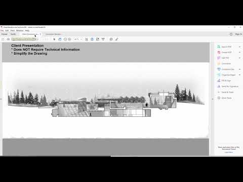
the type of detail you including your drawings often depend on who you will be
presenting the drawings to in this video we will discuss the differences between
the elevations provided to contractors as well as for client presentations open
the drawing named contractor elevations and sections dot PDF elevations and
sections for contractor installations need to include absolutely every piece
of information a contractor may need when building that portion of the
project taking a look at this file we can see a lot of information is provided
all dimensions are provided on the drawing showing details such as the
height of each floor the distance between major occupancy types and
symbols identifying the types of products used in cladding the building
next let's take a look at client elevations and sections PDF client
presentation drawings often do not require all the technical information to
be provided on the drawing it can often be more helpful to simplify the drawing
down so that it could be more easily understood in this PDF you can see an
example of a section that was presented to a client and showcases in a very
simplified version the concept of the project it communicates the atmosphere
and mood rather than the technical rigor of the proposal a similar concept
applies to plans when creating presentation plans you'll often want to
minimize the amount of technical information on the plan so that the
architectural concept is not muffled by all the technical symbols needed by
those who will be installing the project it is important to know who your target
audience is so that you can include the corresponding level of details
accordingly this can often be done in AutoCAD through the use of good layer
management for instance you could place all technical information on specific
layers which can be turned off should you be interested in discussing the work
with a client
you
-------------------------------------------
M9 Video 3 Elevations Furniture - Duration: 4:03.
in this video you will be continuing with the file elevations 3 DWG from the
previous video go ahead and open that now if you do not already have it open
with the walls and windows drawn in the previous video you are now ready to
populate the drawing with furniture in this video you will use the furniture
provided on the right hand side of the drawing to complete the elevation
looking at the floor plan of the bedroom you can see that there is a bed and two
nightstands up against the north wall these are the furniture elements to be
added to the elevation if you take a look at the right-hand side of the
drawing you'll see that I've gone ahead and downloaded a few furniture blocks
that we can use to represent the bed and nights Mane's in this elevation we could
alternatively draw these from scratch however that would take a long time
let's begin by locating the position of the bed draw a vertical line from the
left hand side of the bed in plan view and extend the line down to the
elevation until it passes the line that represents the floor
now select the bed block and move the bottom grip of the bed so that it aligns
with the intersection of the vertical line just drawn and the line that
represents the floor once you're done delete the guide you used in positioning
the bed fantastic your bed is in place next let's do the same steps for the
nightstands draw two vertical lines that will act as a guide for the position of
the nightstands
select the nightstand to buy their grips and place them in their spots
once you're all done go ahead and delete the guides fantastic you have drawn a
completed elevation of the north view from this floorplan this elevation is
fairly simple however if you find yourself drawing more complex elevations
in the future it's good practice to create a library of block resources for
elevation view on the right-hand side of the drawing here where we took the bed
and night stands you can see there are a few more elevation blocks to get you
started if you need more than the blocks available in this file browse the
internet for AutoCAD elevation blocks and save them all in your AutoCAD
template file great go ahead and save your file as elevations for DWG
you
-------------------------------------------
M9 Video 1 Elevations Room Boundry - Duration: 3:53.
geometrically an elevation is a horizontal orthographic projection of a
building onto a vertical plane the vertical plane normally being parallel
to one side of the building architects also use the word elevation as a synonym
for facade so the North elevation is the North facing wall of the building in
this video you will learn to construct interior elevations from a provided
floor plan we will be using the file elevations 1 dot DWG for this video
download it from the current module content folder once you have it open on
the left you will see what your completed elevation will look like once
you've gone through these videos in the middle you will see a floor plan
above and an empty space below which is where we will be drawing the elevation
to the immediate right you will find a number of blocks we will be using for
this tutorial and to the far right you will find blocks that may be helpful
when creating your own elevations in the future if we zoom closely on the bedroom
you will see a new symbol at the center of this room this symbol is often used
on plans to identify elevation drawings the number at the top of the circle is
the elevation drawing number while the number at the bottom is the page where
you will find that elevation the arrow on top of the circle is pointing towards
the elevation that will be drawn in our case it is the North elevation for
example the north interior elevation would be found on page a5 and it would
be the first drawing on that page we need to use these types of symbols
because a fully completed set of architectural drawings can contain many
pages and the use of these symbols helps those searching for the elevations to
find them faster in the construction package ok great
now we're going to draw this North elevation start off by drawing vertical
lines extending from the east and west walls like so
then draw a horizontal line passing through all four vertical lines you had
just previously drawn next copy this floor to thousand three hundred
millimeters upwards
lastly trim all excess lines like so we now have the empty room of our North
elevation we have a wall to the left a wall on the right and the ceiling and
the floor lines above and below save your file as elevations to DWG
you
-------------------------------------------
M10 Video 1 Symbols - Duration: 3:56.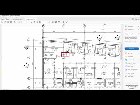
technical architectural drawings often contain an abundance of information
which at times needs to be communicated through symbols and a legend in this
module we will discuss various symbols using the file architectural legend PDF
as well as the file storage lockers PDF go ahead and download these files from
the current module often at the beginning of a document of a
construction set a page with a breakdown of all symbols is included architectural
legends PDF is an example of such a page on this page you will see the major
categories of elements that will contain legends on the architectural drawings in
the package some of the major categories include interior wall assemblies roof
assemblies and floor assemblies if you zoom in closely you will see that each
of these categories are denoted with a circle and a combination of letters and
numbers inside which are commonly referred to as tags now open floorplan
storage lockers PDF as you look at both the interior and exterior walls you will
notice wall tags identifying what each of these walls are composed of let's
take a look at an example if we analyze the exterior wall on the north side of
the building there is wall tag that reads yi6
now if we open architecture legends PDF and take a look under east six of
exterior walls you will see that the wall is denoted as having to our fire
separation and is composed of 100 millimeter rigid insulation and a
hundred ninety millimeter poured-in-place concrete contractors
would read both the floor plan together with the legend so that they could
identify the construction Assembly of the wall using the legend page let's
take a look at another example for this example let's pretend we're a contractor
who will be constructing the walls of the mechanical room on the north side of
the building looking closely at the mechanical room in the plan you will
notice the walls of the mechanical room are denoted as p3 whereas the storage
room walls to the south is denoted as P 11 this means the wall assembly of the
mechanical room and the storage lockers are different
let's check architectural legends PDF of clarification you can see that the wall
p3 is composed of 140 millimeter concrete block while while P 11 is
composed of 190 millimeter concrete block wall assemblies often depend on
fire resistance requirements of certain areas which is outlined in the Ontario
Building Code if this sounds like something you may be interested in a
building code class may be the right choice for you in addition to some of
the symbols you see on this legends page you will most likely come across a few
other symbols as you continue along in your career as an interior decorator the
most notable are Furniture tags furniture tags are very similar to wall
tags in that they contain a small number in combination with a letter confined
within a small geometric shape which is placed beside the furniture
each furniture tag refers to a legend where further information about that
piece of furniture is given such as the location where that furniture can be
purchased the model number and the product number
now you're able to read symbols on floor plans and understand their purpose go
ahead and move on to the next video
you
Không có nhận xét nào:
Đăng nhận xét